Testing
When using the Cortex L4’s ADC, we encountered problems with the consistency of the DU (digital units) being read on Termite (Hyperterminal). In our testing, a steady voltage was sent into the Power Measurement circuit which then dropped our 4 – 24V scale to a 0 – 3.3V, which is a far more suitable range for the MCU. When reading the values from the voltage from the DMM (Digital Multimeter) the values seemed to match those seen in previous tests but when the analogue voltage was converted to DU, the readings were unreliable and had errors up to 350mV.
The power supply seems to be supplying a reliable voltage to the power module, but to make sure we connected an oscilloscope at the two terminals of the supply shown above.
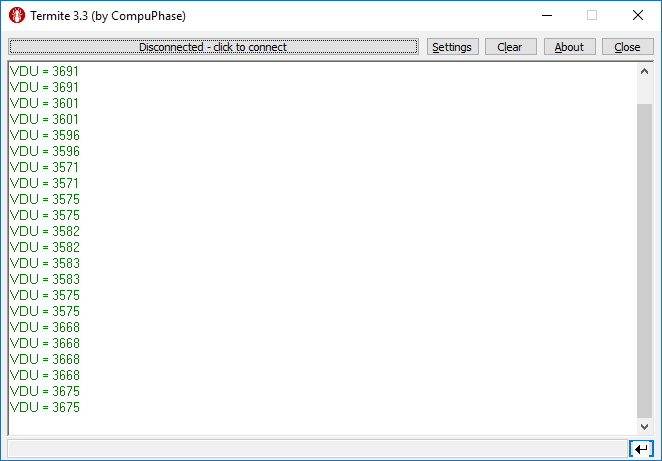
The readings above show the result of sending a constant 6V DC supply into the Power Measurement circuit, the first line is the DU value and the second is DU converted back to voltage to be used to calculate the power. As shown, the DU ranges from 3571 to 3675, a difference of 104.
Assuming a DU range of 0-4095 (12-bit ADC) and a voltage range of 0-24V, these values cause an error of 507mV, an unacceptable error.

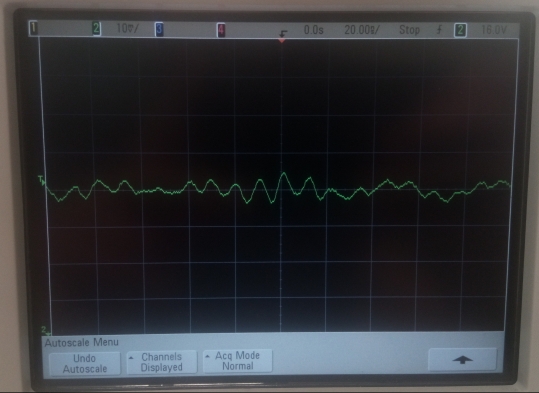
On the top left of the monitor, the voltage scale is shown, each of the verticle lines, in this case, represent 50mV. The oscilloscope shows that the voltage can oscillate between +90mV to -100mV, this explains the large DU jumps when reading from Termite. This wave is also very hard to read due to the large spike only occurring for a very short amount of time.
To ensure the power supply was not at fault we connected the power supply unit to the oscilloscope, spikes either side of the x-axis represent the degree to which the size of the ripple voltage.
The biggest ripple shown above is less than +/- 5mV, this error is acceptable for our application. This suggests that the power module is at fault and not the power supply.
To smooth the output of the power module a capacitor was used, this is often used on rectifiers when converting from AC to DC, a ripple voltage remains and must be smoothed. The differential formula below says that the rate of change of voltage is inversely proportional to the capacitance.

So if the capacitance increases the ripple voltage should be attenuated. To test this an 82nF capacitor was added to the output of the power module (before entering the ADC). When testing with the oscilloscope the waveform below was found.

This waveform brings the ripple down to roughly +/- 40mV, 50mV better than without the capacitor. Our aim is to have a voltage accurate to within 100mV of the actual voltage so a smaller ripple was necessary. The next capacitor used was 1µF, the waveform below is what was shown on the oscilloscope.
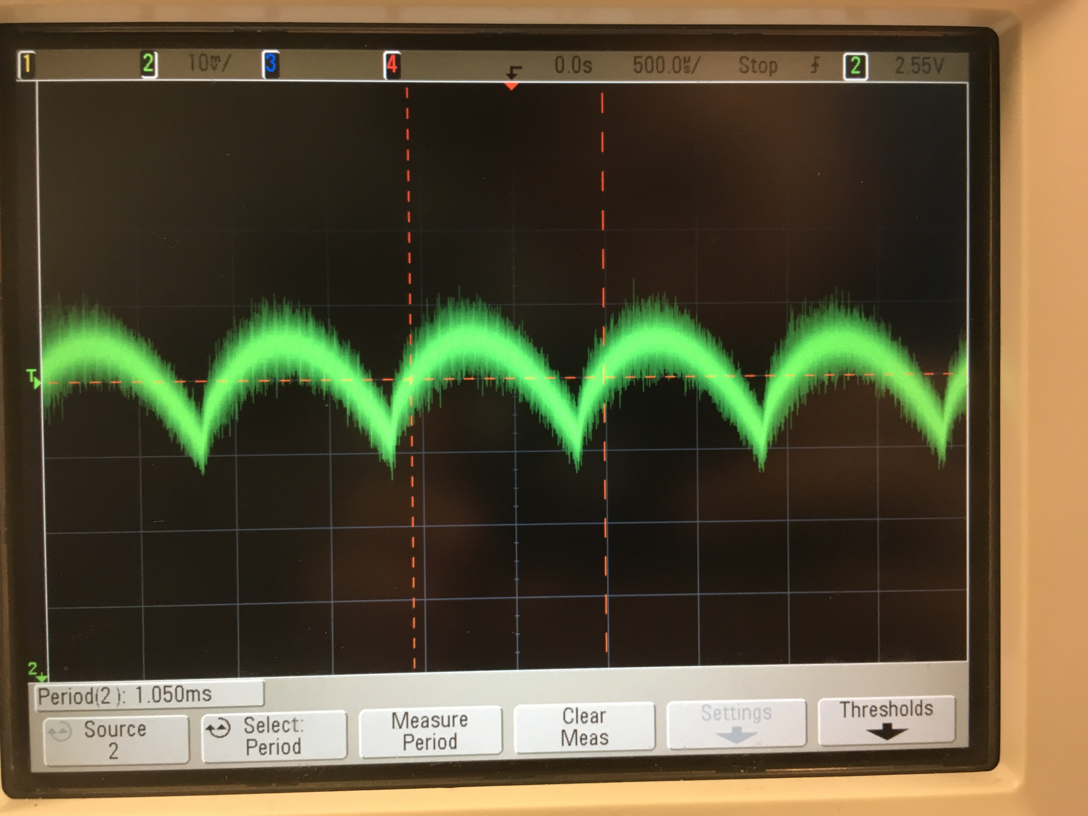
This waveform brings the ripple down to roughly +/- 10mV, 80mV better than without the capacitor. The included capacitor has smoothed the input voltage to the ADC which should, therefore, reduce the spikes in DU read on the Hyperterminal.
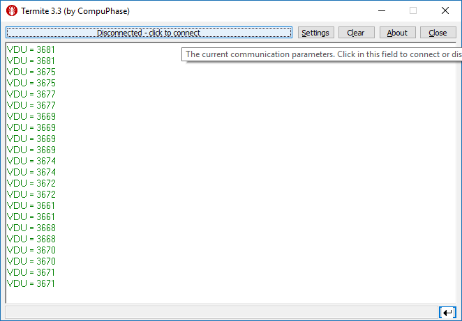
As shown, the DU ranges from 3661 to 3681, a difference of 20. The values above are an improvement from the non-smoothed output but further work needs to be done to achieve an accurate voltage within 100mV comfortably.
Software Compensation
To further improve the accuracy of the system we can use code to get the average of an array that reads in values from the ADC. First an array of integers must be made to store the DU values. Ideally, an infinite number of elements would be used for accuracy but for low power usage, only 16 elements were used.
int ADC_SamplesV[15], N;
float V_Avg = 0;
for(N = 0; N < 15; N++){
  sConfig.Channel = ADC_CHANNEL_5; // The channel that reads voltage
  HAL_ADC_ConfigChannel(&hadc1, &sConfig);
  ADC_SamplesV [N] = Read_Analog_Value(); // DU is added to the array
  V_Avg += ADC_SamplesV [N]; // the Nth element is added to the variable
  HAL_Delay(1);
}
VDU = V_Avg/N; // finds average of all 16 values
The for loop iterates through the ADC_SamplesV array, where the elements are added to a variable, V_Avg. This is done until it reaches its 15th element where it exits the array and the average is found by dividing the sum of the array, V_Avg, by the length of the array, N.
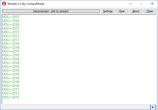
As seen above, the biggest deviation between the values is 5DU, 15 better than the non-compensated system and almost 100 better than the original.
ADC Reference Voltage
Even with the capacitor on the output and the software compensation, there are still some small, unexplained jumps in DU. One reason for this may be the ADC reference voltage which can have a ripple just like the output of the power module.
In our MCU (Cortex L4), a SAR (Successive Approximation Register) approach is used. For this approach, the input voltage is found by continuously comparing the analogue input to the voltage dictated by the SAR.

- SAR Type ADC
If the reference voltage had a ripple of 10mV this would make our reference voltage 3.31V and a given input voltage of 2V would result in an error of approximately 8 digital units. To rectify this problem a capacitor would have to be included just like before, but because these components are within the chip we are unable to solve the problem.
